I am designing and building my own smartwatch from scratch, based around an Arduino microcontroller. I am constructing this watch in the Champaign-Urbana Community Fab Lab, utilizing their tools for digital fabrication: a Roland Modela CNC machine for making the circuit board, an Epilog laser for fabricating the acrylic case, and electronics tools such as soldering irons and SMD reflow stations.
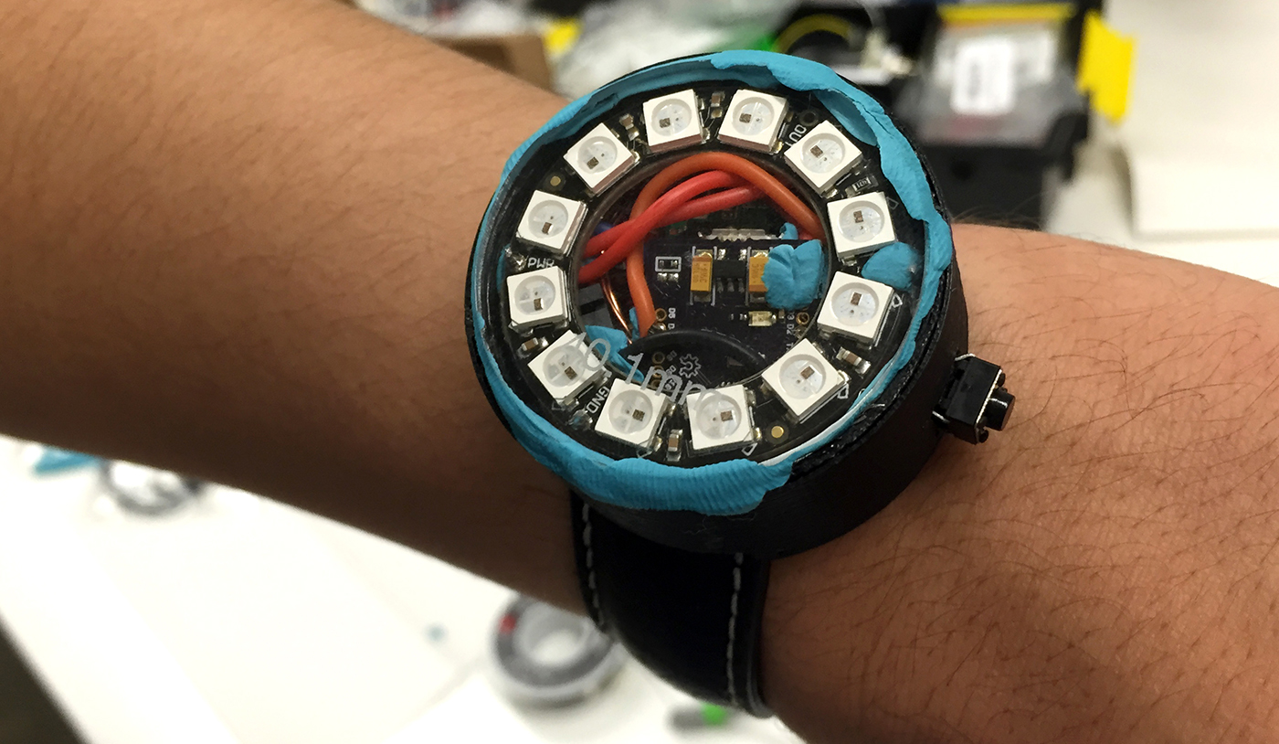
My watch is a roughly 40mm diameter circular device with twelve RGB LEDs. The hour and minute are each represented by a different color. There is a watch crown button on the right side to set the time. It is powered by a lithium polymer battery, which can be charged wirelessly using magnetic induction. The body is 3D printed, and is compatible with standard watch bands attached using spring bars. There is an Arduino-based microcontroller which keeps track of time and controls the LEDs.
I decided on an iterative design process where I would design and build a working simple watch while thinking about expandability, so I could easily modify and add more features. I settled on two basic designs, one with an analog display powered by twelve RGB LEDs, and one with a digital display.
Because I had never built anything like this before, and some of the tools and processes were completely new to me, using an iterative design process where I could build a part of the prototype, see how it worked, go back and improve the design, and make it again, was very helpful and enabled me to learn very quickly. I didn't separate this project into separate design, build, and prototype phases; I did all of these simultaneously.
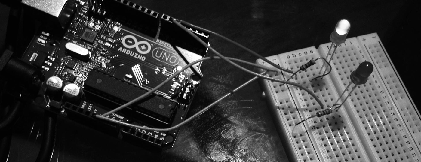
I chose to use Arduino as the microcontroller platform because it is easy to learn, and has a huge community backing due to its open source nature. I had worked with Arduino for a summer internship project at State Farm, so I was familiar with the basics.
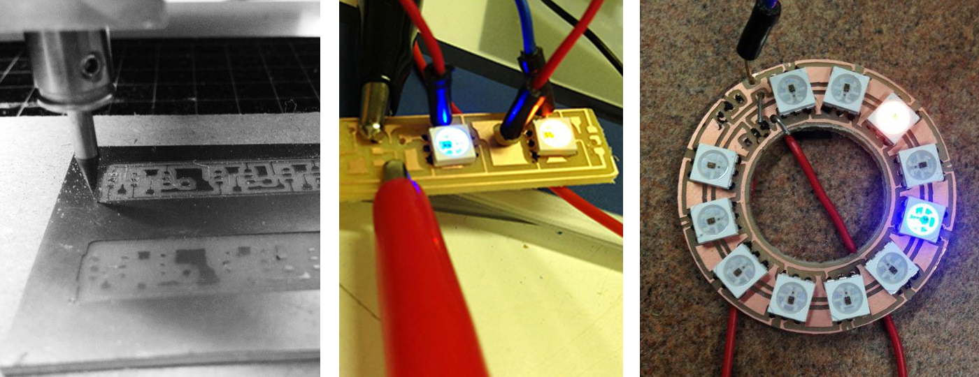
The next step was to figure out which components to use, and how to connect them. At first, I was challenged by the complexity of wiring twelve RGB LEDs, as each one required six connections. However, upon more research, and browsing the components selection on sites such as Adafruit and Sparkfun, I discovered the WS2812 5050 RGB LED with Integrated Driver Chip. This chip only required three connections, power, ground, and data, and could be connected in a chain, with each chip passing the data signal on to the next, with the whole setup requiring only a single I/O pin on the Arduino. The only downside was that I would have to design and fabricate my own custom circuit board for these chips, using nothing but the spec sheet. However, this would later turn out to be a great learning experience.
Now, I needed to find an Arduino-compatible microcontroller in a form factor small enough to fit in a watch. From the beginning, I wanted my watch to be no larger than 40mm in diameter, as that was the diameter of an analog watch that I wear. I also wanted to make it as thin as possible. After doing some Googling, I settled on two possibilities, TinyDuino and FemtoDuino. Both are equivalent to the Arduino Uno, with the same Atmega chip and pins. I decided to go with TinyDuino, as it came in a square 20x20mm form factor, and the corners could be broken off to make it a 20mm diameter circle, perfect for fitting inside a ring of LEDs. Another benefit of TinyDuino is that it can be configured to come with a holder for a coin cell battery.
One major problem I encountered was soldering the tiny surface mount LEDs to my circuit board. I imagined there must be some type of glue-like solder that didn't require heat, and after some research I discovered several products that might help solve my problem; solder glue, conductive paint, and conductive ink. I tried all three, and settled on a process where I used a think wooden stick to apply small amounts of conductive paint to each pad on my circuit board. Next, I would carefully place the LED and apply pressure. After drying, the paint was strong enough to hold the LED in place, and conducted well enough to light the LED.
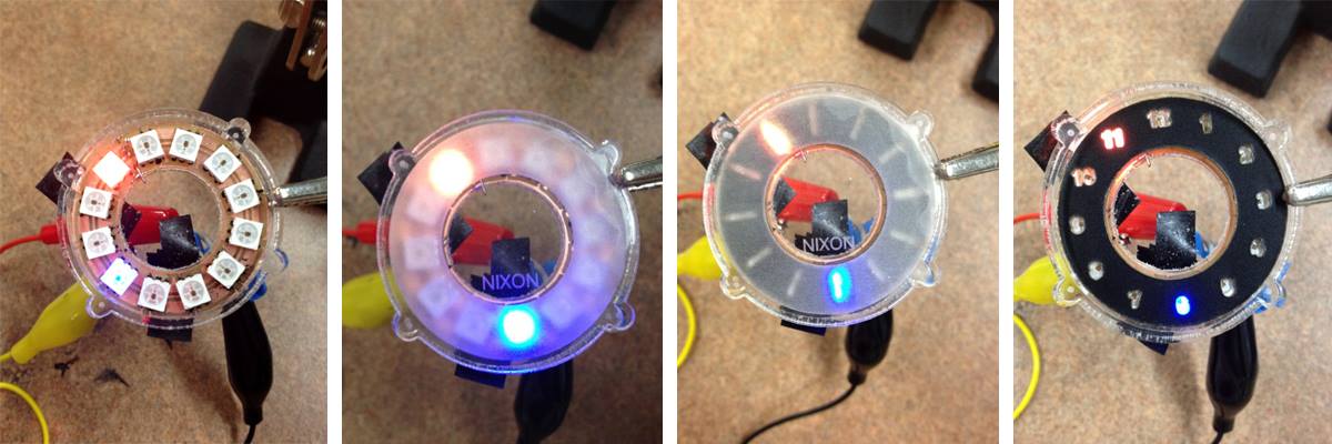
I didn't want my watch face to be just bare LEDs, so I came up with a method using a mask made out of thick black paper or black acrylic to make faces of multiple designs. These faces can be easily swapped out by just removing the cover and swapping out the mask.
At this point I began to think about how the watch band would attach to the body of the watch. I sketched a few designs of my own, and then decided to look at how other watches attached the band. I identified several common methods of attachment, and picked the one that would best fit my design. However, due to the two-dimensional limitations of the laser cutter, it would be very difficult to use this method with a laser cut acrylic case. For this reason, I decided to switch to a 3D printed case.
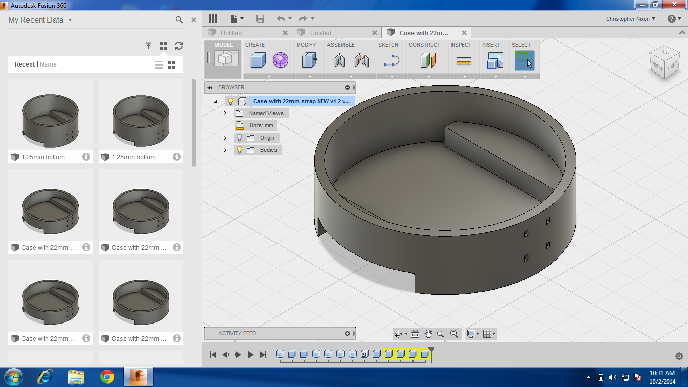
I began designing a case in Autodesk Fusion 360. At this point, because of the increased design flexibility 3D printed afforded, I decided to add a button for a watch crown, to allow me to set the time.
I learned a lot about programming with Arduino, including how to use libraries to draw on the OLED display. I also learned a lot about electronics engineering, how to calculate power consumption, pick components that will work together, and figure out how to make them work together. I also learned how to design and fabricate a custom circuit board, using both a Roland Modela CNC machine and copper-coated fiberglass, as well as using an Epilog Laser to etch a circuit into Indium Tin Oxide coated PET film.